Description of the project
The E-cube project manages all energy exchanges, from a technological point of view (recognition of the subjects, authorization for the transfer and withdrawal, measurement of the energy exchanged, consistency with the constraints imposed for load management and for the minimum energy in the storage devices etc.) and for the related economic aspects (definition of the exchange value, debit and credit, balance transactions, etc.). The name of “Banca dell’Energia”, given to the System, is therefore clearly motivated by the close similarity of the operations described above with those typical of a credit institution.
The purpose
The extensive use of the "System" generates benefits in terms of energy efficiency and, consequently, in economic terms which are shared between Enegan and its customers, through appropriate participation contracts in the Bank, generating margins for Enegan and lower costs of the energy bill for the customers.
Objectives
The primary objective of energy efficiency and better use of green energy in itself already entails direct results of important social value, regarding the reduction of greenhouse gas emissions and the consumption of non-renewable fossil fuels.
Other advantages will be obtained, albeit with a long-term perspective, such as:
- a contribution to the development of electric mobility, which is an important tool for the reduction of fossil fuel consumption;
- a contribution to the solution of critical issues due to the presence of generation plants from non-programmable renewable sources which are becoming increasingly important for the management of distribution networks.
The problems that the Energy Bank System aims to contribute to solving derive, directly or indirectly, from the developments that have characterized the National Energy System (SEN) in recent years and that lead experts to speak of a real "change paradigm ".
For a detailed analysis of this transformation, the benefits and critical issues that derive from it and for a full understanding of the design idea, it is necessary to schematically summarize these opportunities / conditions that generated the design idea:
- in the last decade, in Italy, the National Electricity System (SEN) has gone from a few thousand to around 700,000 GFR plants with a total installed power of around 28 GW and growth is expected to continue at these rates also in the coming years;
- this great development has made it possible to achieve the environmental protection objectives established by international bodies and to lighten the country's dependence on imports of fossil fuels;
- The number of electric vehicles circulating in Italy, despite the delay compared to other countries, is expected to grow strongly mainly of the plug-in type but with the tendency to be exceeded by wireless charging systems.
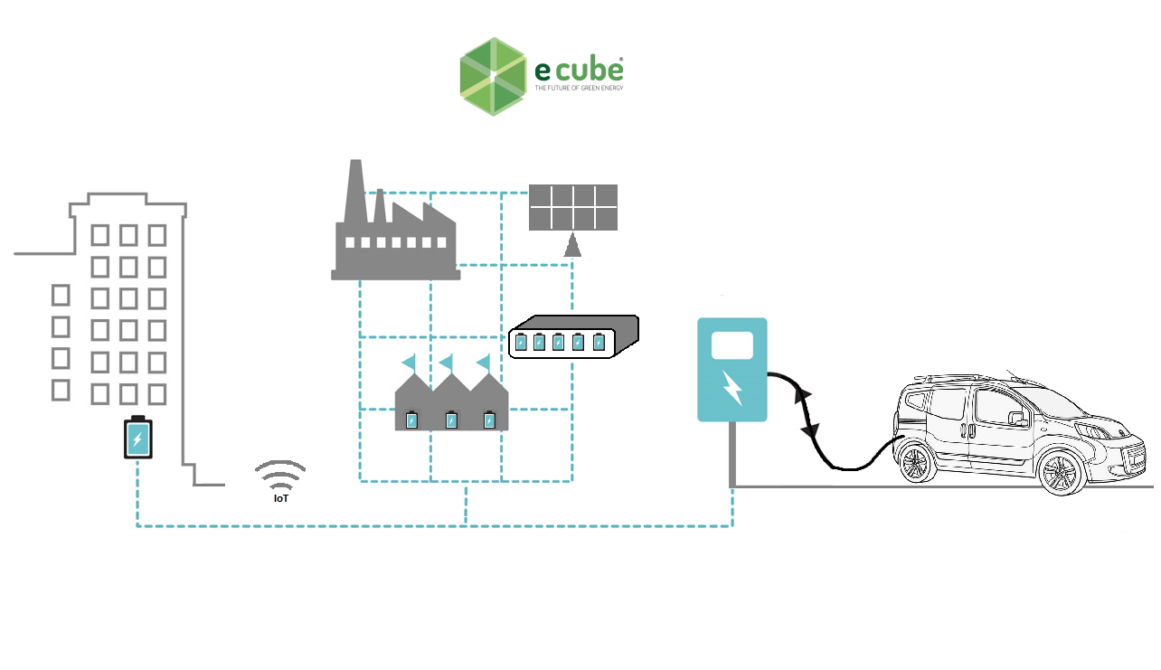
The E-cube project team faces the problems described above through the design and testing of a prototype of an Energy Bank System and associated technologies that optimize energy flows within a "community" of its customers , called to make available their generation and storage resources, accepting the management of their consumption / production by Enegan, in view of mutual economic benefits.
With this objective, the E-cube team will have to carry out studies and developments aimed at acquiring technological tools that allow to carry on the design idea and the demonstration of effective effectiveness, such as:
Forecast statistical analytical models for the optimization of energy exchanges and the development of an optimal control system for energy storage / exchange systems,
communication and energy management systems, bank management and user management,
bidirectional systems for storage / supply of energy from renewable sources,
Battery charging systems both plug-in and bidirectional wireless charging.
The automatic exchange of information coming from the equipment and the integration of functions and integrated systems connected together in aggregations that concern production and consumption, responds to the organizational methods envisaged in Industry 4.0 thanks to the exploitation of the new frontiers of digital techniques.
In particular, E-cube creates a production (energy) and commercial ("bank") system capable of managing, interpreting and enhancing the large amount of data available thanks to the use of digital technologies, supported by powerful analytical calculation methods needed on models.
One more reason
In a note of October 2016, ARPAT (Regional Environmental Protection Agency of Tuscany) underlines how: "In 2050, electric vehicles powered by renewable sources will cover 80% of the car fleet on an EU scale with a reduction equal to about 10% of the total annual CO2 emissions. Overall, additional electric power of 150 GW will be required to recharge electric cars, most of which obtained from renewable sources. This increase will have to be accompanied by the strengthening of the networks and the creation of the necessary infrastructures, such as for example charging stations”. In line with what indicated by this authoritative body, the E-cube project responds perfectly to what is foreseen.
The Subsystems
The "Energy Bank" project is divided into subsystems which are interconnected with each other through the most suitable technologies and standards (Web, WiFi, G4 / G5, LAN, LPWAN, etc.) and perform macro-functionality. The subsystems mentioned above are:
Bank Management Subsystem
Energy Management Subsystem
User Management Subsystem
Social Subsystem
BMSS
The Bank Management Subsystem implements an Energy Bank and is responsible for verifying and recording energy transactions between prosumers.
EMSS
The Energy Management Subsystem has the task of managing and coordinating the actions of energy exchanges and represents the real brain of the System.
UMSS
The User Management Subsystem consists of the set of devices for monitoring and control (smart meters, storage and actuators).
SCSS
The Social Subsystem has the task of supporting the community and making the various users interact in order to maximize awareness.
The roles of the partners within the Project
Enegan Spa: participates in research and system engineering activities; takes care of the design and implementation of the system prototype, in particular for the Bank Management Subsystem (SSGB), for the User Management Subsystem (SSGU), for the Mobile Storage Device (DAM) and the two-way wireless charging stations; participates in system integration, experimentation and dissemination of results;
Ergon Srl: participates in research and system engineering activities; takes care of the design and implementation of the System prototype, in particular for the Energy Management Subsystem (SSGE); participates in system integration and experimentation;
Giuneco Srl: participates in research and system engineering activities; takes care of the design and implementation of the System prototype, in particular for the management software for wireless charging and communication stations; participates in system integration and experimentation;
Department of Information Engineering of the University of Florence (DINFO): participates in research and system engineering activities, in particular for the research and definition of big data analysis modeling of user profiles for the management of energy, for the forecast of consumption and for the energy transfer modeling of the wireless charging station; takes care of the design and implementation of the System prototype, in particular for the creation of the software / firmware for controlling the energy transfer of the wireless charging station; participates in the integration of the system and experimentation.
Greenapes: participates in research and system engineering activities; takes care of the design and implementation of the system prototype, in particular for the Social Subsystem (SSSC); participates in system integration and experimentation;
BMSS
The Bank Management Subsystem, managed by Enegan, has the task of verifying and recording the energy transactions, among the prosumers, which are required by the other subsystems of the platform and of recording the corresponding economic transactions. This SS has the task of receiving and processing information in real time from the User Management SS regarding energy exchange transactions and accounts for energy transactions between Customers and the rewards deriving from transactions carried out by each member of the community. The BMSS regulates the "balance" of the operations at pre-established deadlines, connecting with the management system for administrative operations and also regulates relations with the other energy providers who contract charging users outside the Energy Bank community, while charging the electric vehicle.


EMSS
The Energy Management Subsystem, managed by Enegan, Ergon and UniFi DINFO, has the task of coordinating the various actions and represents the real brain of the present invention. Enegan brought his knowledge of energy exchange methods and supplies to the project of this SS. Ergon contributed with his own specialist skills in business management systems and database management. UniFi Dinfo represents the expert in the development of simulation models and algorithms for predicting consumption profiles. The SSGB uses a blockchain and the economic transactions are managed in the form of tokens owned by the wallets of each User (Prosumer).
UMSS
The User Management Subsystem is managed by Enegan and UniFi DINFO. Enegan will bring its knowledge of energy management systems to the project of this SS, instead UniFi Dinfo will bring its skills on telemeasure devices and for the design of any devices that cannot be supplied on the market. The UMSS has the main task of managing the sending of commands and collection to the local devices installed at the customers and of managing the exchange of data between EMSS and BMSS and consists of the set of devices for monitoring and control ( smart meters, storage and actuators) of user operations as well as from the EVCS (Electric Vehicle Charging Station) both wireline and wireless.


SCSS
The Social Subsystem has the task of supporting the community and making the various users interact in order to maximize awareness of the use of energy and environmental protection. The primary reason for the existence of the SSSC derives from the need to activate and maintain in the Customers those active participation behaviors that constitute a key element for the functioning of the System. The experience made by Enegan in the collaboration already underway with Greenapes shows that, for these purposes, involvement with the typical methods of the web-communities has an importance at least equivalent to the economic benefits that could derive from participation in the Energy Bank.
The types of User for which the Energy Bank system was designed are:
Smart
They are users who own, or could own, a production plant from FR, are equipped with special meters for energy consumption (smart meters), are equipped, or could be equipped with storage systems, and are owners, or could be equipped, of a charging station.
Storage
They are users who are already equipped with, or could be equipped with, storage systems, are equipped with specific meters for energy consumption (smart meters) and are owners, or could be equipped with a charging station.
Costumer
They are single users, or groups of users, belonging to the same POD equipped with specific meters for energy consumption (smart meter).
Flywheel
They are single users, or groups of users, which are equipped with special actuators for the remote control of energy-intensive loads and specific meters for energy consumption (smart meter).
The DAM
For the correct functioning of the system, the DAM (Mobile Storage Device) has been designed, it is a mobile device with V2G (Vehicle To Grid) functionality that interfaces with the electricity network or with FR (Renewable Source), through both traditional and a wireless system. Its purpose is to physically go to a critical point where energy is scarce or abundant and consequently charges or discharges through its batteries in order to optimize energy in the network.
Architecture of DAM
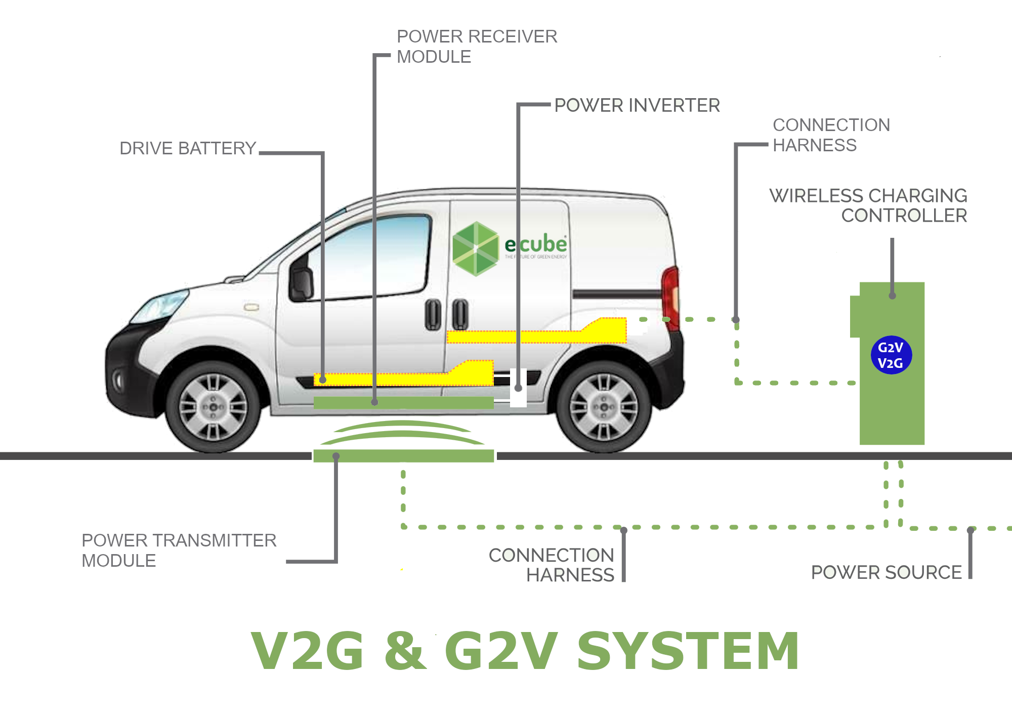
The DAM bi-directional charging system is composed of the following elements:
- A charging station with cable connection to the vehicle, with custom connector and support both for charging the vehicle and for transferring energy from the vehicle to the station (V2G functionality, or vehicle to grid).
- A uni-directional wireless charging system, installed on the ground.
- Control electronics on board the vehicle, which will coordinate the different charging / discharging modes available and interfaces with BMS and battery charger on the vehicle via data line.
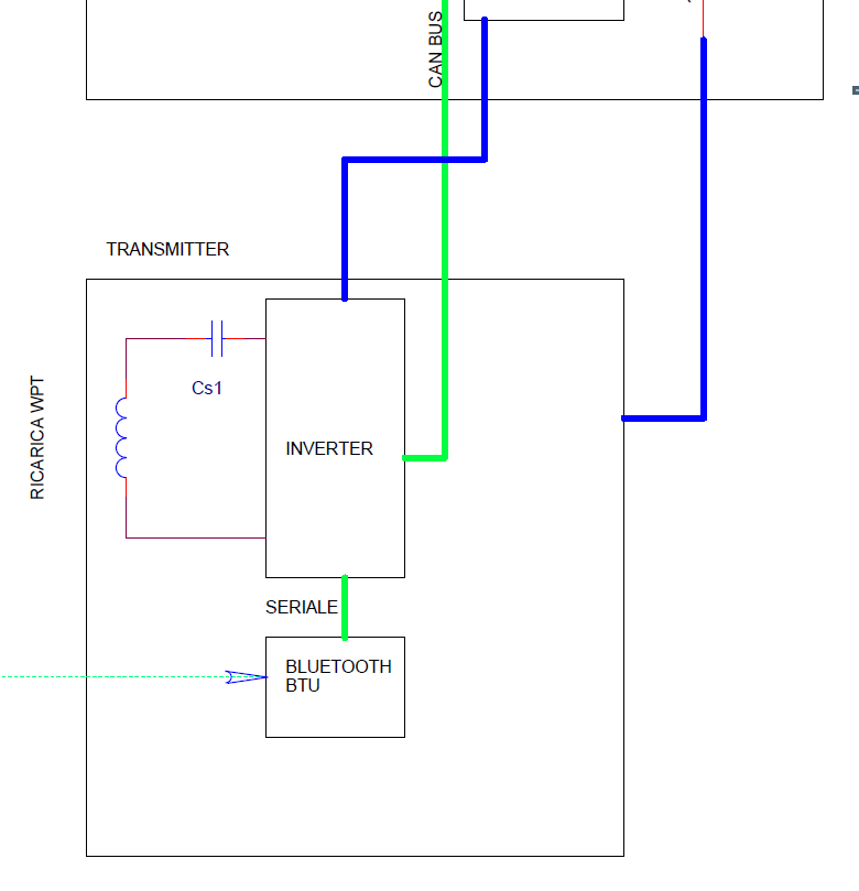
The block and electrical diagram of the system in detail of the DAM are shown below.
Bi-directional charging system with energy storage
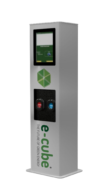
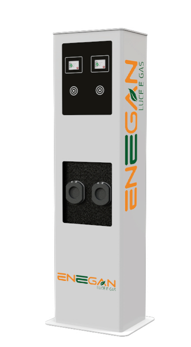
The charging station is equipped with a connector with a custom cable to allow, on command, to recharge the vehicle in accordance with mode 3, or to transfer energy from the vehicle to the network.
Charging control, both during charging and discharging, takes place through the communication stack for controlling the station via OCPP 1.6 (Open Charge Point Protocol), which has been expanded with custom functions for V2G functionality, including where:
- identification of the Customer who connects (via station mounted RFID reader or via remote transaction sent by the server).
- start / close of the "recharge" or "supply" operating mode, available to the Customer through the OCPP custom function
- communication with the SSGB for sending the transaction data.
The station is equipped with an LCD display for the user interface, RFID reader and is prepared for connection to the network via ethernet.
Charging Stations for the V2G charging system
Bi-directional Charging Station
Energy storage
Wireless induction charging
The wireless charging system allows you to transmit energy to the vehicle (up to a maximum power of c.a 1000W) through the principle of induction charging, without, that is, cable connection between the vehicle and the charging system. Charging power has been successfully tested up to 1 kW. It is therefore a system indicated in situations of medium / long stops such as those that occur for company vehicles during periods of inactivity (e.g. at night).
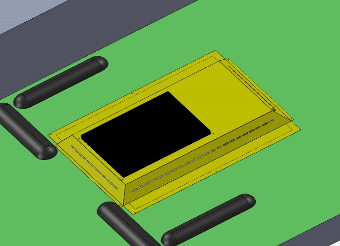
The wireless charging system consists of 2 modules, respectively a platform on the ground (transmitter) and one on the vehicle (receiver).
The system has been sized to guarantee maximum transfer efficiency at a distance of approx. 15 cm between Transmitter and Receiver. It should be noted that this distance was determined as the smallest distance capable of ensuring at the same time a high transfer efficiency (> 80%) and an adequate space between the bottom of the vehicle (in particular the Receiver device fixed on the bottom) and the street level.
In addition, numerous experimental tests were carried out in order to determine the dependence of the transfer efficiency on parameters such as the variation in the distance between Transmitter and Receiver, translational dis-alignments and rotational dis-alignments.
Once the nominal distance (15 cm) has been set, the changes that the system can undergo over time will reduce this distance (e.g. if the vehicle tires deflate), which would benefit the efficiency of the system. On the other hand, the rotational misalignments between the Transmitter and the Receiver are limited by the geometry of the system and the mounting on a 4-wheeled vehicle (the situation would be very different, for example, in the case of a system applied to the charging of motorcycles).
The only parameter capable of significantly influencing the efficiency of the system is the transactional alignment between the 2 systems, as confirmed by the experimental tests.
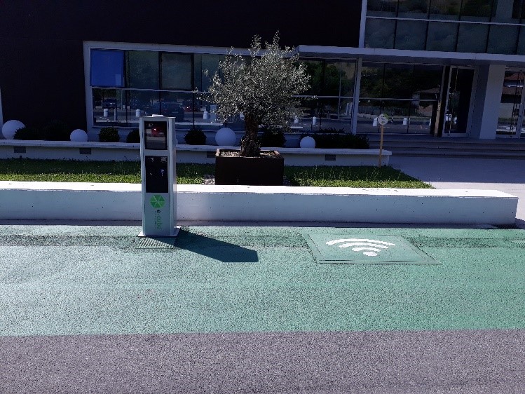
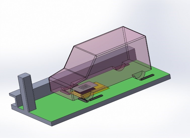
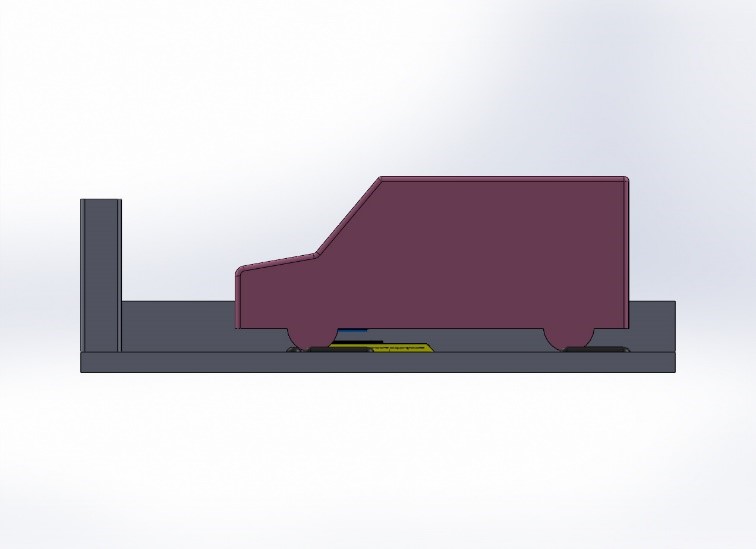
Experimental tests have shown that in order to allow an optimal transfer of energy it is necessary to guarantee a correct alignment between the Transmitter and Receiver devices. For this reason, a centering system has been designed that allows optimal alignment. The centering system allows the user to park the vehicle in an optimal position and to start charging simply from the column display.
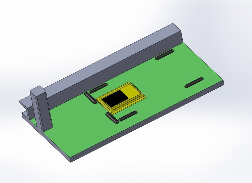
The mechanical design of the transmitter provides for a housing in a structure on the back, to allow the distance between the Transmitter and Receiver to be reduced without sacrificing the height of the vehicle from the street level during circulation. Furthermore, on the Transmitter there are status LEDs that allow the user to immediately check the charging status.
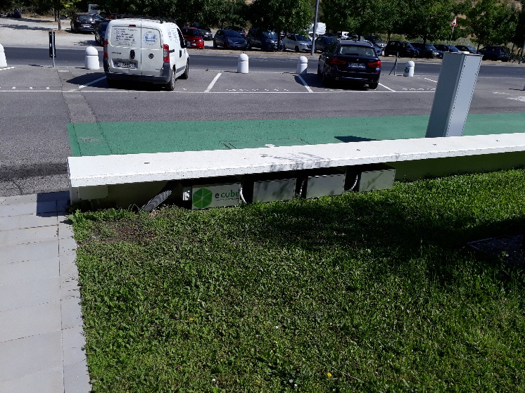
Positioning of the vehicle on the Wireless charging system in the following two figures
Reached Results
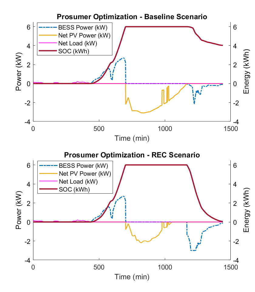
The picture 1 shows us two graphs: the top one shows the typical values assumed in the Baseline scenario in a simulation day by the main variables related to the prosumer, such as SOC (t), the power produced by FV, the charging power and storage discharge and power of prosumer loads; in the graph below the same variables are reported for the same simulation day but in the EC (Energy Community) scenario.
Pic. 1: trend of the main status parameters of the Prosumer in the Baseline and EC scenarios.
The SOC reduction at the end of the day is evident, as is the overall reduction in the PV power surplus. This is one of the main results of the energy exchanges that take place within the EC and leads directly to an increase in the prosumer's earnings. A side effect related to the use of part of the storage capacity for energy exchanges within the EC, is a possible small increase in the prosumer's purchase of energy from the grid.
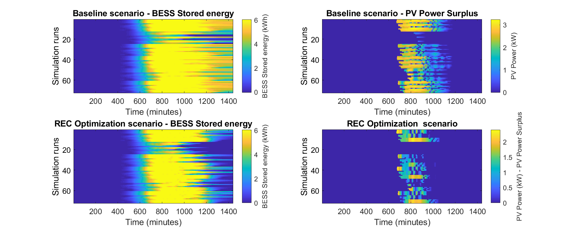
SOC (t) trends over 72 periods measured in 1 day are shown in the graphs on the right. They are analyzed for both scenarios. From the graphs (pic. 2) it is clear that the end-of-day SOC of storage is constantly reduced in the CE scenario compared to the Baseline; this confirms that the algorithm works correctly in all the situations analyzed. Looking at the same graphs, it can be seen how the PV power surplus left after the optimization is completely reduced in the CE scenario in all periods.
Picture 2: SOC performance of storage and PV generation surplus after sharing with the EC for the various days of the simulation.
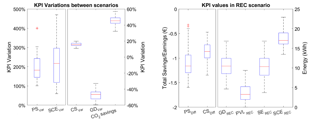
Picture 3: statistical trend of the main KPIs related to simulation.
Finally, an analysis of the values of the KPIs, as shown in picture 3, provided an overview of the improvements related to the implementation of the proposed EC optimization model: first, the dependence on the grid for electricity is reduced on average by over 40%, and consequently the CO2 savings share has increased. In absolute terms this translates into an average of around 10 kWh / day of electricity shared within the Community.
In addition, self-consumption, on average, increases more than twice, moving from the Baseline scenario, in which only prosumers are involved in optimization, to the CE scenario, in which consumers are also. This translates into over 15 kWh / day of self-consumption within the EC, of which around 10 kWh / day are shared and the rest is used by the prosumer. Taking into account the economy of the operation, the result is rather positive, given that the gains of the prosumer in the CE scenario are, on average, almost two times higher than those of the base scenario, and the savings of consumers are around 15 ÷ 20%.
The CO2 savings linked to the reduction in the purchase of energy from the network is directly proportional to it; for the calculation, the 2018 CO2 intensity of the Italian Fuel Mix was used for the production of electricity, for a value of 303 gCO2eq / kWh (emission factor from Ispra).


